Vacuum sensor
| Part 7 of the build documentation. You may want to check out the intro first. |
The machine has two MPXV5050VC6T1 vacuum sensors. These go down to -50kPa. For reference: the atmospheric pressure at sea level is about 100kPa. The solution shown here will also work with the MPXV6115V that goes down to -115kPa i.e. a complete vacuum at atmospheric pressure. My experiments so far with the regulated vacuum show that even a fraction of the -50kPa is enough. But to be on the safe side or if you have a stronger/unregulated vacuum, get the MPXV6115V.
The first sensor measures the pressure in the nozzle after the valve. It is used by OpenPNP to determine if parts are picked up and released right. The second sensor monitors the pressure in a metal bottle that serves as a “vacuum reservoir”. The vacuum pump runs on a hysteresis (bang-bang) to keep the vacuum at a certain range.
The Smoothieboard has inputs for thermistors that are normally used for monitoring extruder temperatures in 3D printers. These go well above 200°C so the thermistors exhibit a wide range of resistance. The standard Epcos resistor will have less than 5% of its 25°C 100kΩ value at the highest temperatures. To get a good voltage range, the pull-up resistor (top part of the resistor divider) in a Smoothieboard is only 4.7kΩ on a 3.3V input. Furthermore there is a large 10µF capacitor. See the relevant detail of the Smoothieboard schematic here:
The MPXV5050VC6T1 has an output range of 0.1V (-50kPa vacuum) to 4.6V (ambient pressure), so it has to be adapted to the 3.3V range. At the lowest value, the sensor would have to pull down the 4.7kΩ resistor to ~0.1V, so almost 700µA would flow (thank you Marek T. :). However the sensor can only drive 100µA max (see the series datasheet). What’s more, because of the stiff pull-up resistance, the needed voltage shift, and the large input capacitor, a very low value resistor divider would be needed to get a reasonably large voltage swing (i.e. good ADC resolution) and reasonable settle time. The sensor cannot drive it directly (unless you’re prepared to modify your Smoothieboard).
So we need to voltage shift and buffer the output using an op-amp. This will also create a low impedance signal that will not pick up too much noise.
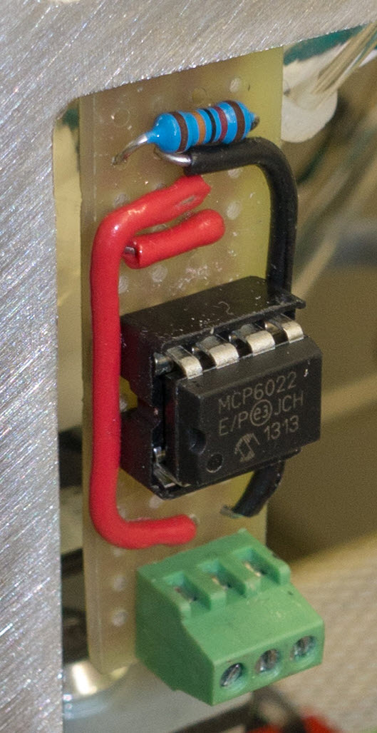
Scraping together DIL through-hole, some 0805 smd parts and a strip-board I made the following. Update: JulienD made a real PCB. Check it out here →.
Note that the (dual) op-amp is mirrored in this image, as it is mounted on the other side. Mentally connect the yellow dots to the pins to see how the circuit works.
The turquoise lines show where strip-board traces must be cut. I also cut all traces underneath the sensor so none of the 5 .. 8 pins are connected. But I don’t know if this is really needed.
Red and black lines/dots show the power supply wire connections on the other side.
I just had a dual op-amp in DIL laying around so I made the first one buffer the sensor output, then used a R/2-to-R resistor divider to shift from 5V to 3.3V, then used the second op-amp to buffer this. The first op-amp is not really needed, if you just have a single op-amp IC (pinout changes!). The output op-amp needs to be able to source and sink ~5mA at a minimum for charging the Smoothieboard thermistor input capacitor in reasonable time. Use a rail-to-rail I/O op-amp to be sure it works on the full input and output voltage range.
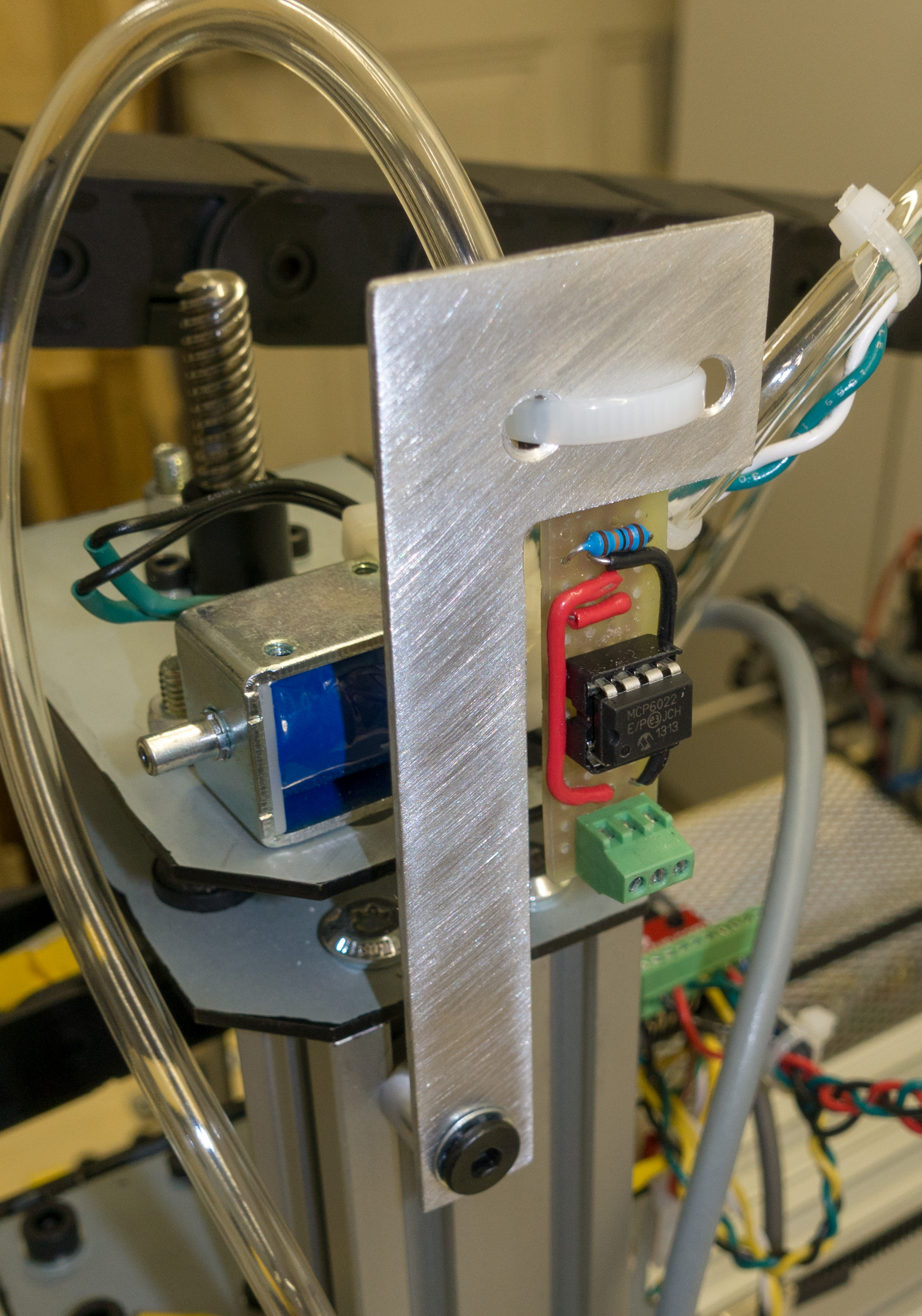
My R is 100kΩ, C is 0.1µF but similar values are fine, I guess. I just had an MCP6022 10MHz op-amp in DIL, that’s overkill in bandwidth, but it works of course.
I added a 470Ω series output resistor for op-amp stability when driving the large 10µF input capacitor and for some crude protection of outputs (and inputs) if you short things or connect to the wrong pin on your Smoothieboard.
I hope the needed supply wire connections and the single through hole R resistor (that eliminates the need for a crossover wire) are clear, when you see the front side (more pictures further down).
The following shows a simple simulation circuit I made (after the fact):
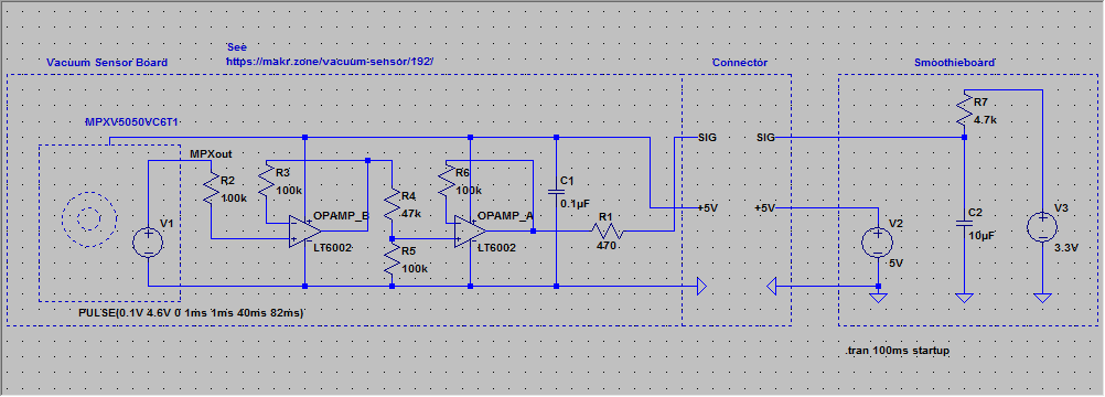
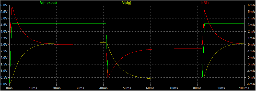
The simulation shows how the sensor output (green) is voltage-shiftet to the Smoothie thermistor input (yellow). Because of the large 10µF Smoothieboard input capacitor, considerable currents (~5mA) will flow, if you want the vacuum signal to change in a reasonable time (red):
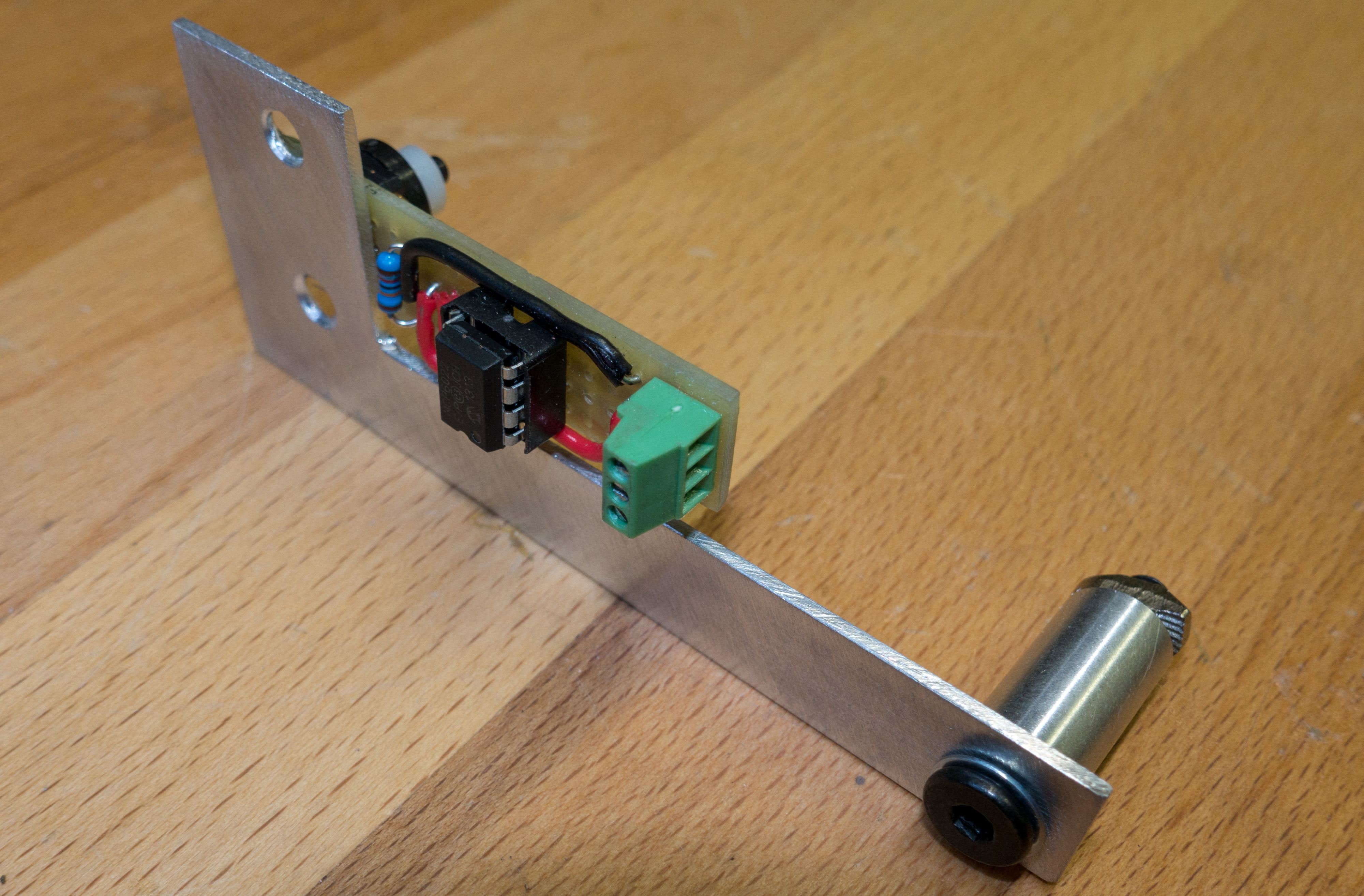
The L-shaped aluminium plate that holds the sensor is hot-glued to the PCB. The aluminium need to be pre-heated using a hot air gun for the glue to stick.
When I prototyped the circuit I just melted a hole in the vacuum tube with my solder iron tip, then stuck the sensor in using a nylon spacer to limit the insertion to prevent blockage. This worked so well, I kept it as a the final solution, saving a lot of space for reduction adapters, Y connectors etc. There is no leakage whatsoever. This may not work with all tube materials, the one that comes with the Liteplacer kit is very soft and sticky and creates a perfect seal. A zip-tie is used to hold the tube in place gently.
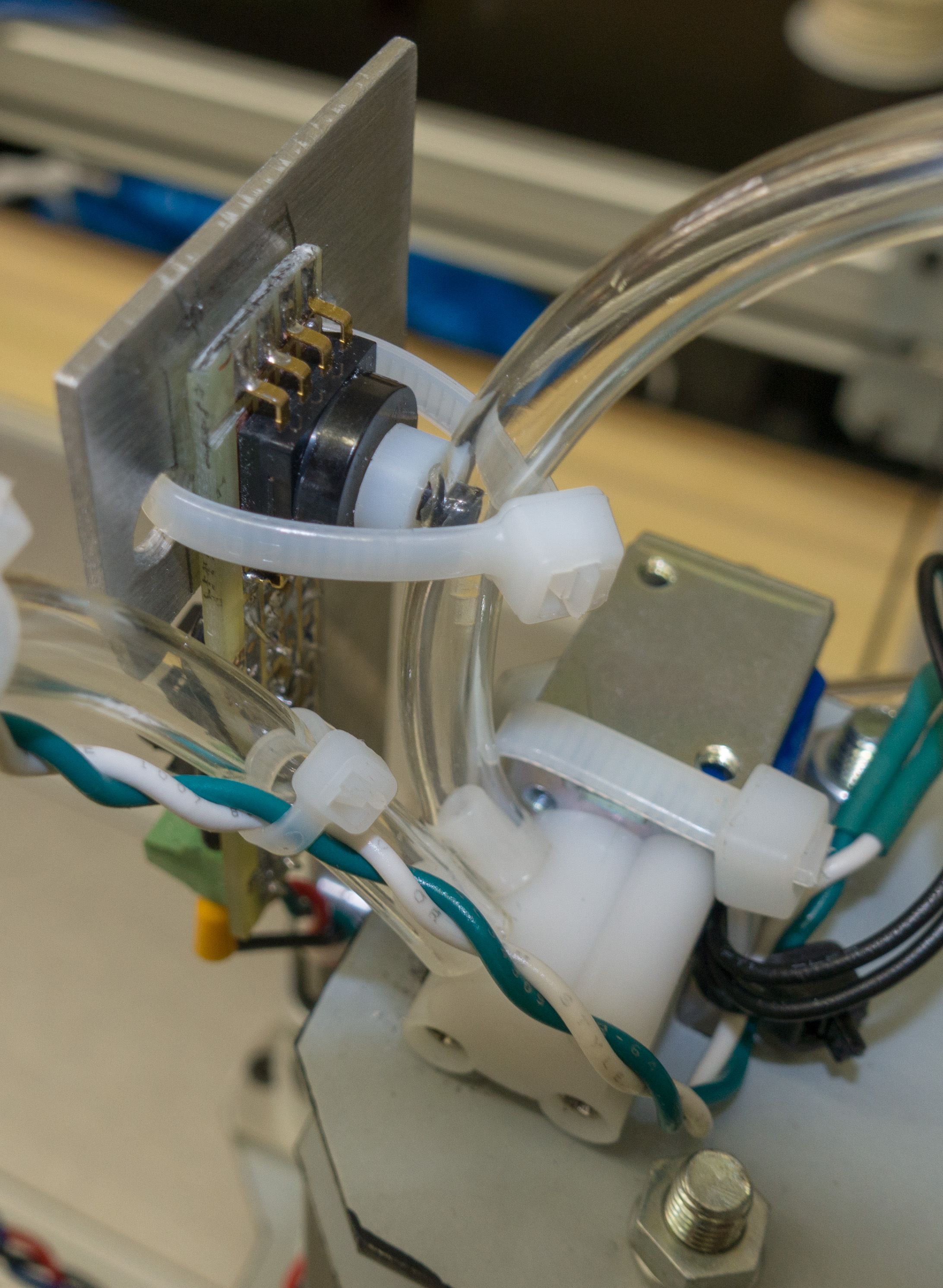
For the valve connection, see also the Liteplacer instructions.
These are the corresponding Smoothieware config.txt temperature control settings:
temperature_control.pump.enable true #
temperature_control.pump.thermistor_pin 0.23 #
temperature_control.pump.heater_pin 2.7 #
temperature_control.pump.designator B #
temperature_control.pump.min_temp -10 #
temperature_control.pump.max_temp 300 #
temperature_control.pump.thermistor EPCOS100K # see http://smoothieware.org/temperaturecontrol#toc5
temperature_control.pump.bang_bang true # set to true to use bang bang control rather than PID
temperature_control.pump.hysteresis 5.0 # set to the temperature in degrees C to use as hysteresis when
temperature_control.pump.runaway_heating_timeout 0 # it seems to crash
temperature_control.pump.runaway_range 0 # a rapid delta in temp triggers a halt - 0 disables it
temperature_control.pump.set_m_code 140 #
temperature_control.pump.set_and_wait_m_code 190 #


temperature_control.nozzle.enable true #
temperature_control.nozzle.thermistor_pin 0.25 #
temperature_control.nozzle.heater_pin nc #
temperature_control.nozzle.designator V #
temperature_control.nozzle.min_temp -10 #
temperature_control.nozzle.max_temp 300 #
temperature_control.nozzle.thermistor EPCOS100K # see http://smoothieware.org/temperaturecontrol#toc5
temperature_control.nozzle.runaway_heating_timeout 0 # it seems to crash
temperature_control.nozzle.runaway_range 0 # a rapid delta in temp triggers a halt - 0 disables it
temperature_control.nozzle.readings_per_second 320 # smoothieware takes the median out of the last 32 measurements, so read frequently
Of course the Smoothieware will handle the measurements as °C on an obscure thermistor curve (not kPa). But the value range covered is wide (~25 is ambient pressure, ~190 the maximum my pump can reach). The signal is quite stable and with good resolution. It just so happens that 100 seems to be a good setting for the vacuum reservoir set-point.
To read and act on the values in OpenPNP, use the Setup Guide for Vacuum Sensing.
temperature_control.nozzle.designator V
ACTUATOR_READ_COMMAND:
M105 ; read all temperatures and vacuum levels
ACTUATOR_READ_REGEX:
^ok.*V:(?<Value>-?\d+\.\d+).*
UPDATE 2021-11-16:
If you have multiple nozzles, be sure to number the .nozzle. part in the config and use a different designator for each nozzle.
temperature_control.nozzle1.enable true #
...
temperature_control.nozzle1.designator V #
and
temperature_control.nozzle2.enable true #
...
temperature_control.nozzle2.designator W #
etc.
And likewise, adapt the designator V in the regex.
Credits:
- Go mostly to Malte Randt’s build:
https://www.liteplacer.com/phpBB/viewtopic.php?f=11&t=175&p=1161&hilit=mrandt+vacuum+reservoir#p1532
Leave a Reply