The “Non-Kit” Assembly
| Part 6 of the build documentation. You may want to check out the intro first. |

I’m used to woodworking, so making the wooden base was OK. But then for the metal work…
Switching from the nicely prepared kit to my own contraptions was a shock.
It started with the ordering process. A nightmare of shipping costs, long delivery times or – alternatively – brutal Swiss pricing. Not being a regular “mechanical maker” meant ordering a lot of basic hardware and tools. I always forgot one thing or other.
Designing and making the custom details proved to be way more complicated and time consuming than anticipated.
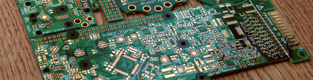
The PCB Carriage
The PCB carriage for instance had to be extremely flat, to provide a 40mm (2 x extrusion grid) headroom to the table surface. I had to do it in a elaborate aluminium + magnetic stainless steel sandwich design with cut-outs for the stepper and actuator end-plates to just barely slide by.
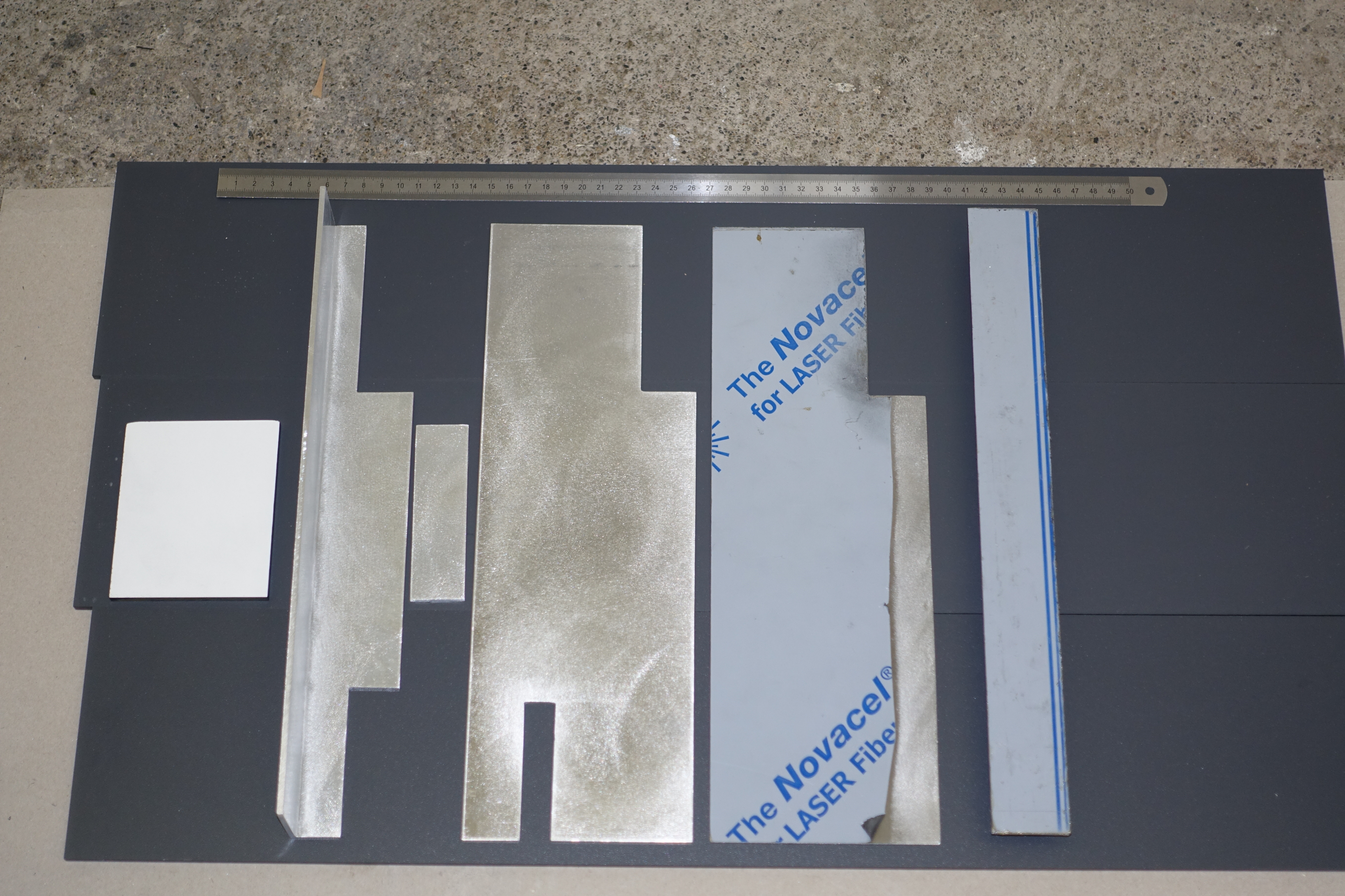

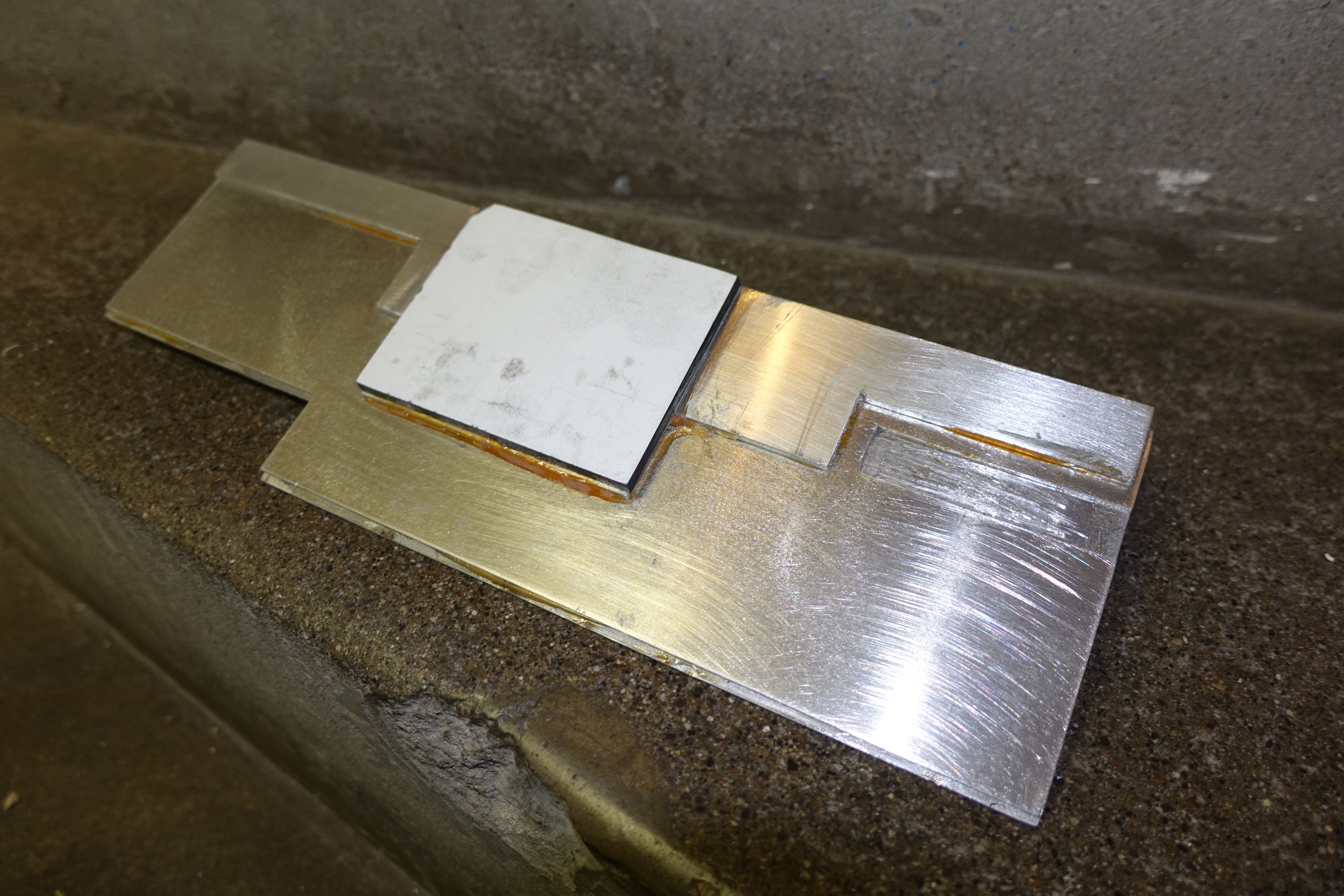
I even had to file down the stepper motor a bit (see next image) as the carriage goes all the way to the edge!
In the end I think this turned out quite OK. The glued sandwich design is extremely sturdy, the stiffness of the aluminium somehow complementing the toughness of the stainless steel. The 3mm thick angled profile “backbone” on one side and the two component adhesive between all of it seems to make it indestructible. All the cut-outs and the thin composition reduce weight. Not a wobble!
The Bottom Camera Scare
Then another scare: I completely underestimated the needed focal distance for the bottom camera. So I had to fit it inside the gap besides the actuator. Just by pure luck the ELP 6mm 2MP Full HD High Speed MJPEG USB Camera Module happened to be a few millimetres smaller.
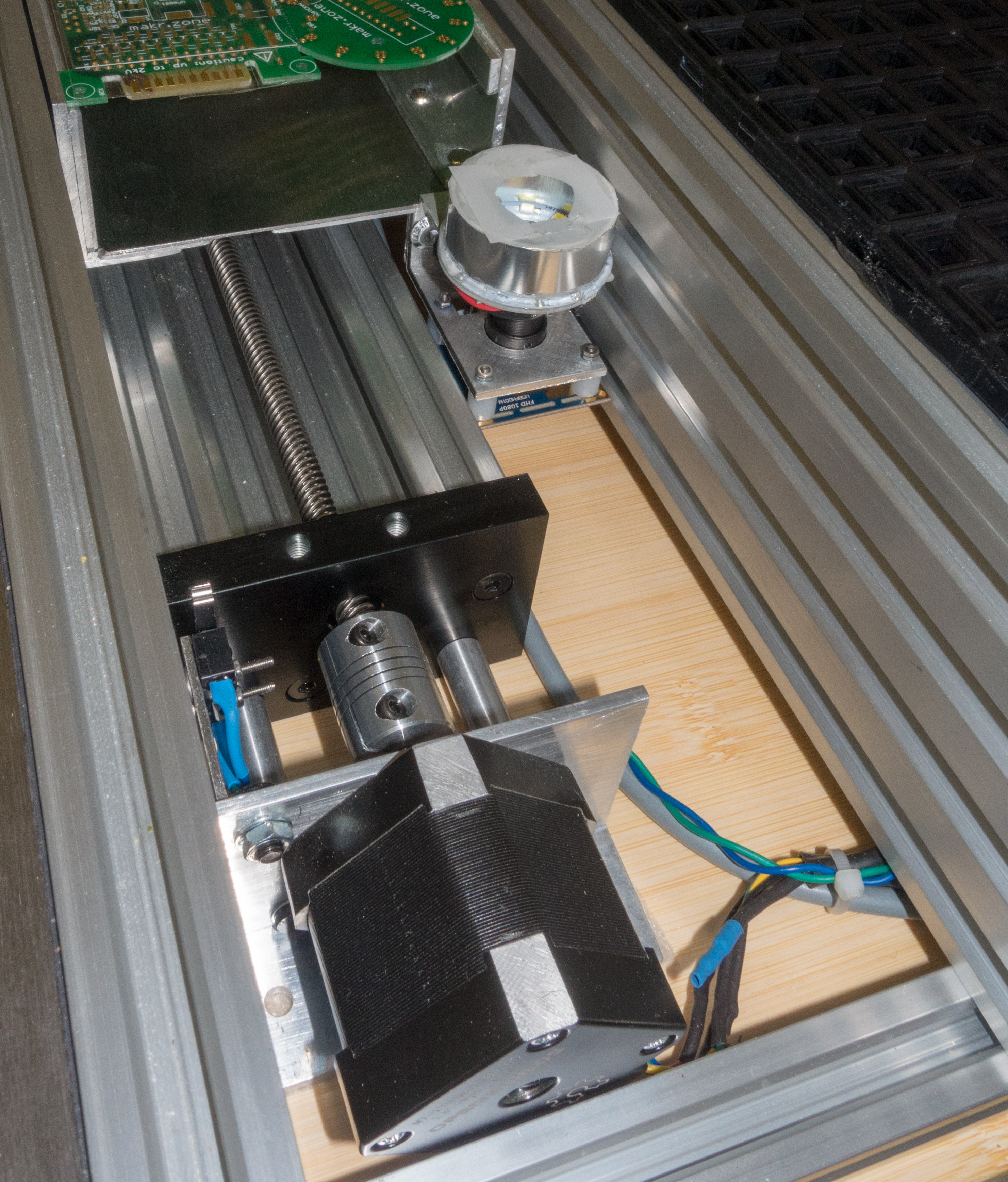
Upgrading the Y Motor
The OpenBuilds Lead Screw Actuator comes with a NEMA 23 motor. That’s way too much power for this purpose.
On the other hand I was always thinking about upgrading the kit Y motor (a 0.9° NEMA 17 stepper). The Y motor has to drive two belts and two gantries on both sides of the machine plus the weight of all the other axes (remember the pyramid?).
The same size motor is used for the X axis, driven by just one belt, one gantry with only the much lighter head to move. Easy to see there is a mismatch, not unlike the power ratio between NEMA 17 and 23.
To swap out the motors I needed to make a custom “plate” to mount the smaller stepper to the lead screw actuator. I was able to use standard OpenBuilds parts to mount the NEMA 23 motor for the Y axis. The motor remains stationary so there is no trade-off of increased weight:

In the end I chose to use 1.8° OpenBuilds NEMA17 stepper motors for the lead screw actuator and the X axis. More about the reasons in a future post.
Leave a Reply