Choosing a Motion Controller: The Panucatt Azteeg X5 GT 32bit
Most motion controllers today use a universal language called G-Code, a de-facto standard that incredibly dates back to 1950. G-code mainly just moves mechanical axes around in a completely abstracted manner, so you should be able to do anything with it, right? Does it even matter, which controller to choose?
Assuming you want an Open Source controller, those were mainly developed with 3D printing and/or CNC milling and perhaps Laser cutting in mind. These applications are quite different from Pick&Place and this sometimes results in unexpected hiccups. Sometimes it is a small detail that will make a controller unfit for OpenPnP.
Your first stop should therefore be the OpenPnP “Motion Controller Firmwares” Wiki page. Multiple controller firmwares are presented and their pros and cons quickly discussed. When I evaluated my controller, the page recommended against the TinyG that came with my Liteplacer and a Smoothieware based controller was favored (today you have many more good options, like the Duet controllers). Smoothieware is a firmware and hardware design that is Open Source, so a number of clones exist besides the original Smoothieboard.
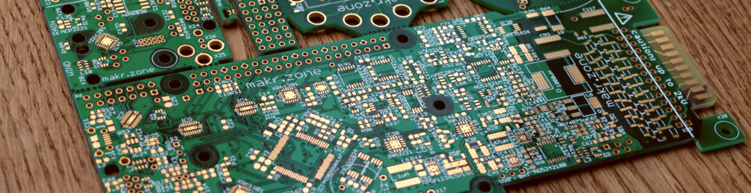
The Panucatt Azteeg X5 GT 32bit
So I looked for the board with the best options for the task and found the Panucatt Azteeg X5 GT 32bit with Bigfoot BSD2660 driver boards. I donated to the Smoothieware project as a compensation for not buying the board there.
The convincing features were those:
- Modular driver design: Drivers can be selected from a wide range and replaced when damaged.
- Two driver socket standards: Bigfoot and the maker Pololu style (with optional extra digipot control)
- SPI control for Bigfoot drivers (Trinamic TMC2660)
- Separate voltage rail for the drivers up to 35V.
- Extra thick outer copper layer (2oz) for high stepper currents and no ground bouncing.
- Isolated USB, your machine ground is separated from the computer.
- On-board high efficiency DC-DC for 5V (MCU) and 12V (typical for camera LEDs).
- Fuses, input/output protections, the right connectors, etc. clearly a well-designed board.
- Compact size, clean layout, connectors well organized.
My evaluation was two years ago, but compared to the available controllers known to me today, I’m still very happy with the Panucatt Azteeg X5 GT 32bit. In fact, I feel it finally gained the interest it deserves in the OpenPnP group recently.
Supply Power and Grounding
The Azteeg X5 GT has a well engineered power and grounding concept. Power for the MCU comes through the on-board DC-DC converter from the machine PSU i.e. the machine will stay controlled and homed if you unplug the USB port. Likewise, if the machine PSU is not powered, the USB won’t power up the MCU against a dead machine. Most importantly the USB is isolated, so there will be no ground bouncing or other problems. I’m running it on a 5 m USB cable with no issues. For contrast read this Smothieboard section:
A few things to be careful of to avoid USB disconnections :
Make sure your USB cable is as short as possible (less than 50 centimeters or two feet is ideal), is shielded, and ideally has ferrite beads.
Make sure your machine and the computer controlling it are plugged into the same power strip.
Make sure your local electrical installation is not subject to variations and interference.
Make sure there are no large motors, fridges, neon bulbs or other strong sources of electrical interference in the same room.If all of those rules are applied, USB will work fine in the vast majority of cases.
More about this in the animated OpenPnP group discussion.
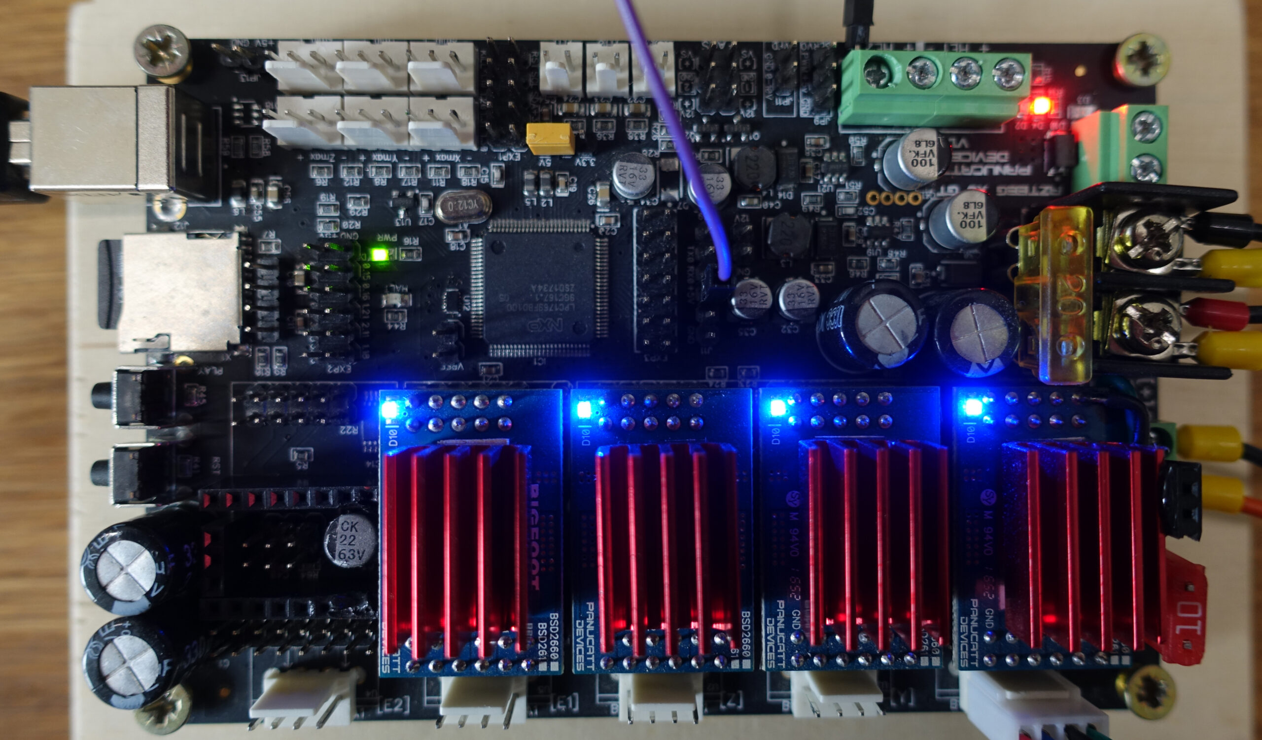
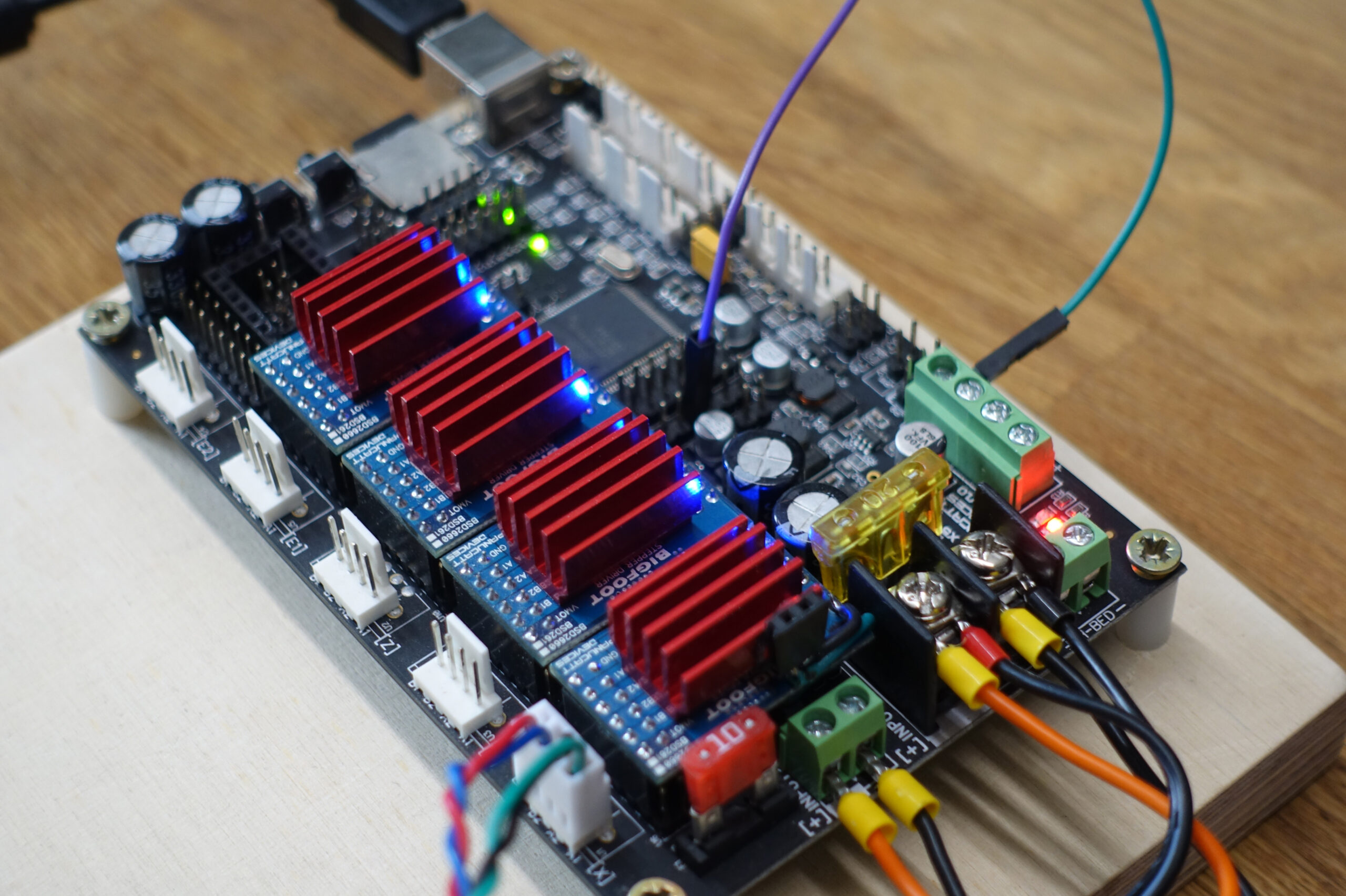
Important note about the photos: I mounted the red heat sinks 90° wrong, as I thought it would be better for air flow with the board mounted vertically. But it turns out there are vias conducting the heat that should be covered. The heat sinks should form a single line across. I later damaged one driver and its socket by inserting it backwards (holy smoke!). So I replaced the board in the machine with a new one where I mounted the heat sinks the right way. :-) The old board now serves for testing and development. The incident does not seem to have fazed it. Rock stable.
Higher Voltage, please!
At the time I was overvaluing the current capabilities of the drivers (hefty 4A for the TMC2660). Turns out that for Pick&Place, current is not so important, but voltage is. At the high speeds that are wanted, the steppers exhibit a high impedance through what is called the Counter-electromotive force or “Back EMF”. Current will hardly go through anymore. The practical remedy is higher voltages. The Panucatt has a separate voltage rail and 35V spec, so it is prepared to a degree (Bigfoot BSD2660 drivers have 30V max). Because I didn’t know that at the time, I currently have 24V on both rails. The extra 6V sound like little, but they should improve the speed limit quite a lot.
In the diagrams from the excellent article “Stepper motor torque basics” (By Eric Rice, Applied Motion Products) the relationship becomes clear, if you cut across the voltage curves with a horizontal line (specific required axis driving torque) to see where each voltage sets the attainable speed limit.
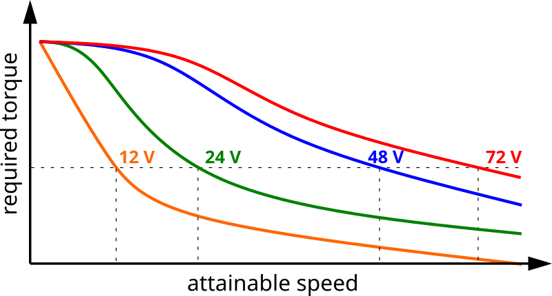
Attainable speed given a specific required torque (approx. curves from mentioned article).
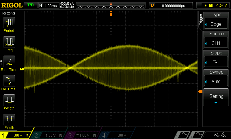
The following are measurements of the current (from the driver’s sensing resistor x 10, ~1A/V).
First for slow operation (Note the 1V≈1A unit):
Then for very fast operation (Note the 5 times lower 200mV≈200mA unit, 5 times smaller time unit):
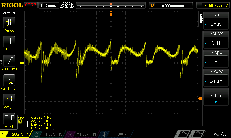
For more info, read the Trinamic Application Note, specifically section 2.5 “High Velocity Optimization”.
Tuning the drivers
I spent a lot of time tuning the TMC2660 stepper drivers. The control of a gazillion option through SPI is cool, but you can lose yourself in them :-).
Some of the famous Trinamic technologies don’t really result in large benefits for PnP high speed operation, so in retrospect I would spend much less time on those.
I wasn’t able to set achieve large coolStep™ savings, i.e. the ability to turn up or down the motor current with the load. PnP moves are sharp stop and go, the coolStep™ current scaling takes some time to servo in, so it only works with slow transitions at lower-to-middle speeds. Like I’ve shown above, the current will drop to a few hundred milliamps at high speeds so raising the current limit clearly does not help. Strangely the TMC2660 does not support a simple STEP based still-stand detection (see section 5.1.2 of the data sheet). I think this was improved in newer TMC models.
I was able to set up stallGuard™ as a crude crash detection (that saved the machine from larger damage a few times since) but not for detecting skipped steps. Again this works well at lower speeds but not when the steppers already are near the limit at high speeds.
Most important and successful was the tuning of the spreadCycle™ i.e. the so-called chopper that modulates the current through the motor coils, by switching their polarity or shorting them in elaborate sequence. The tuning improved achievable top speeds by more than a factor 2 over the default IC/Smoothieware settings. I was also able to reproduce the superiority against the classical constant T-off chopper that other drivers still use.
For more info about how a stepper works, I recommend this video:
Config
Configuration is a very complex topic, so I can’t cover details here. Instead, please use my config as a template (linked below). The TMC2660 data sheet and Application Notes and Smoothie’s Advanced Driver documentation are sometimes very terse and you have to research and try out things to really understand.
Many of the settings can only be set through G-Code, so you need to put a on_boot.gcode file on the SD drive and enable it in config.txt.
on_boot_gcode_enable true
These are my current files:
Please feel free to ask about specifics.
What would I do differently?
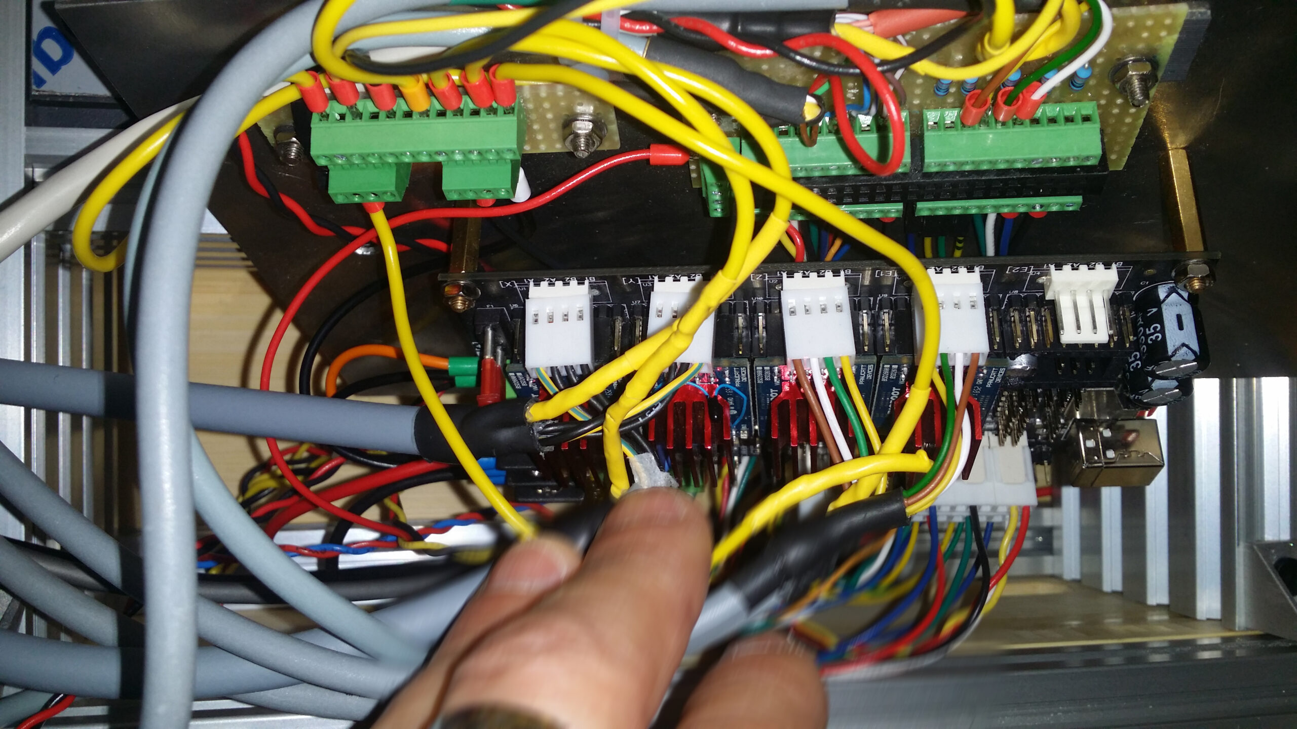
Definitely don’t put your controller in a tight compartment in the far corner of your machine (and of the room), even if that is the natural spot for the cable chain to start.
You will be absolutely amazed how quickly the cabling adds up to form this gargantuan snake pit. Don’t add pointless LEDs for all the end stops and FETs, like I did. It was a hassle and huge work connecting those and hardly any value added.
Comments are always welcome!
(page updated slightly 2023-01-05)
Leave a Reply