Design of the Machine Base
| Part 4 of the build documentation. You may want to check out the intro first. |
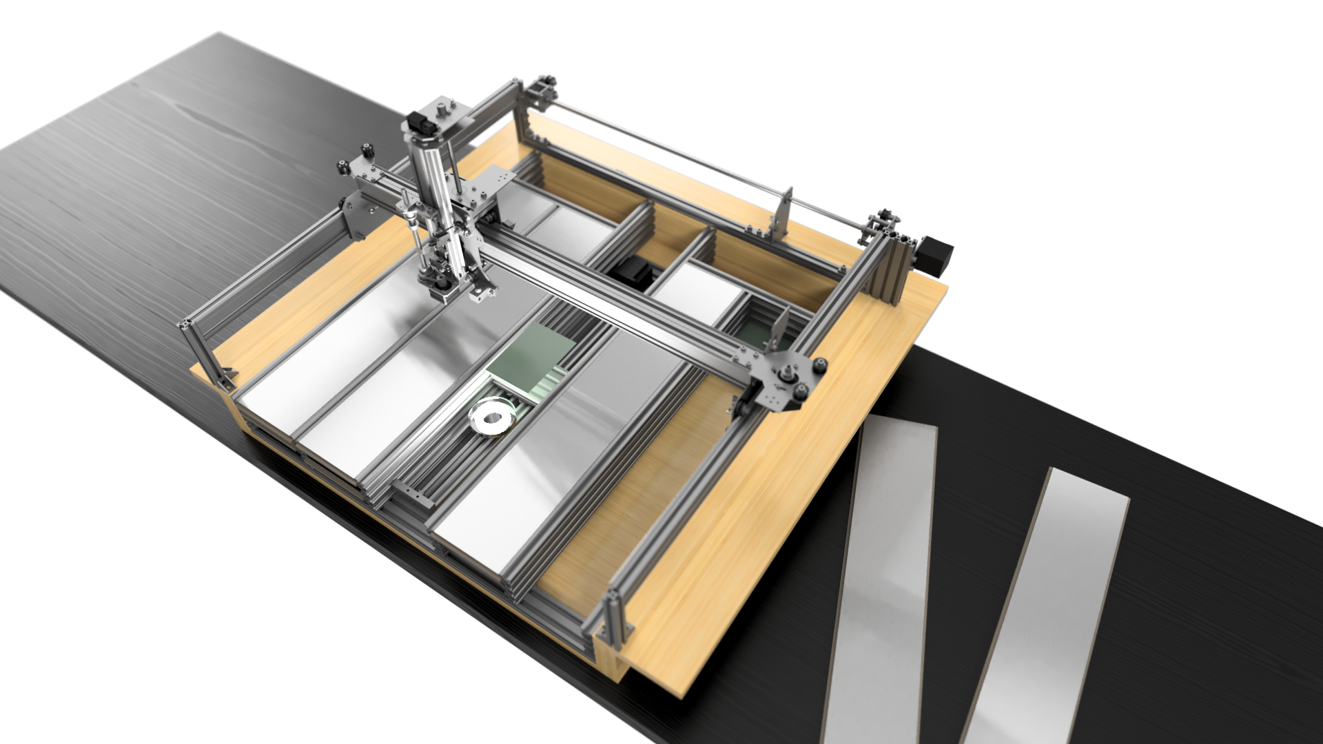
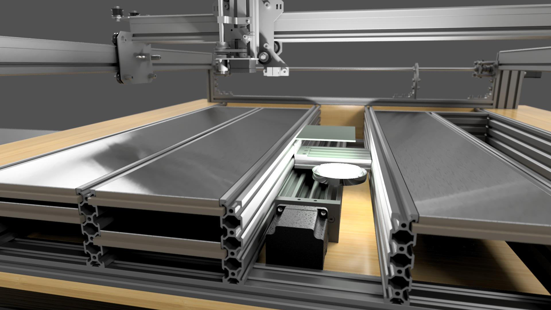
With the idea of the PCB conveyor finally crystallised, I started to design a special base for the Liteplacer. It followed these design targets:
- PCB conveyor as already discussed.
- Bottom camera moves with PCB, always close.
- Removable, multi-level slate design, for storing and externally preparing feeders for multiple projects.
- Open frame design for double sided + manual through hole PCB assembly.
- Stand-alone sturdy machine base to be able to move and turn around the machine for better access to all sides (cramped workshop, corner position).
I visualized this with Fusion360, using the Liteplacer CAD model and the OpenBuilds Parts Library. The conveyor is simply designed with a Lead Screw Linear Actuator.
The real work could begin.
Leave a Reply