Planning the Work Area
| Part 3 of the build documentation. You may want to check out the intro first. |
From the theory discussed in the last part, I knew the Y axis will most likely be the bottleneck of this machine. The following questions popped up:
- Can I arrange PCB, parts, camera etc. to make the critical Y moves shorter?
- Can I make sure my X moves (accelerations) are not unnecessarily limited by Y’s?
- Can I simply add a bigger Y motor?
- Are there any better solutions?
I really needed to think about how the work area will be arranged.
Planning the Work Area
The original Liteplacer is already larger in X (750mm extrusions) than in Y (500mm extrusions). This favours X moves naturally. The Liteplacer article “Plan Your Work Area” suggests an arrangement similar to this (simplified for illustration, green PCB, grey-patterned feeder area):

Assuming the worst case “full table” scenario, your part feeders (strips, etc.) are equally distributed across the work area. With equal distribution you can take the centroid as the average part position. This gives you average pick distances (“deltas” in X and Y) of half the work area dimensions, plus half the PCB width in X.
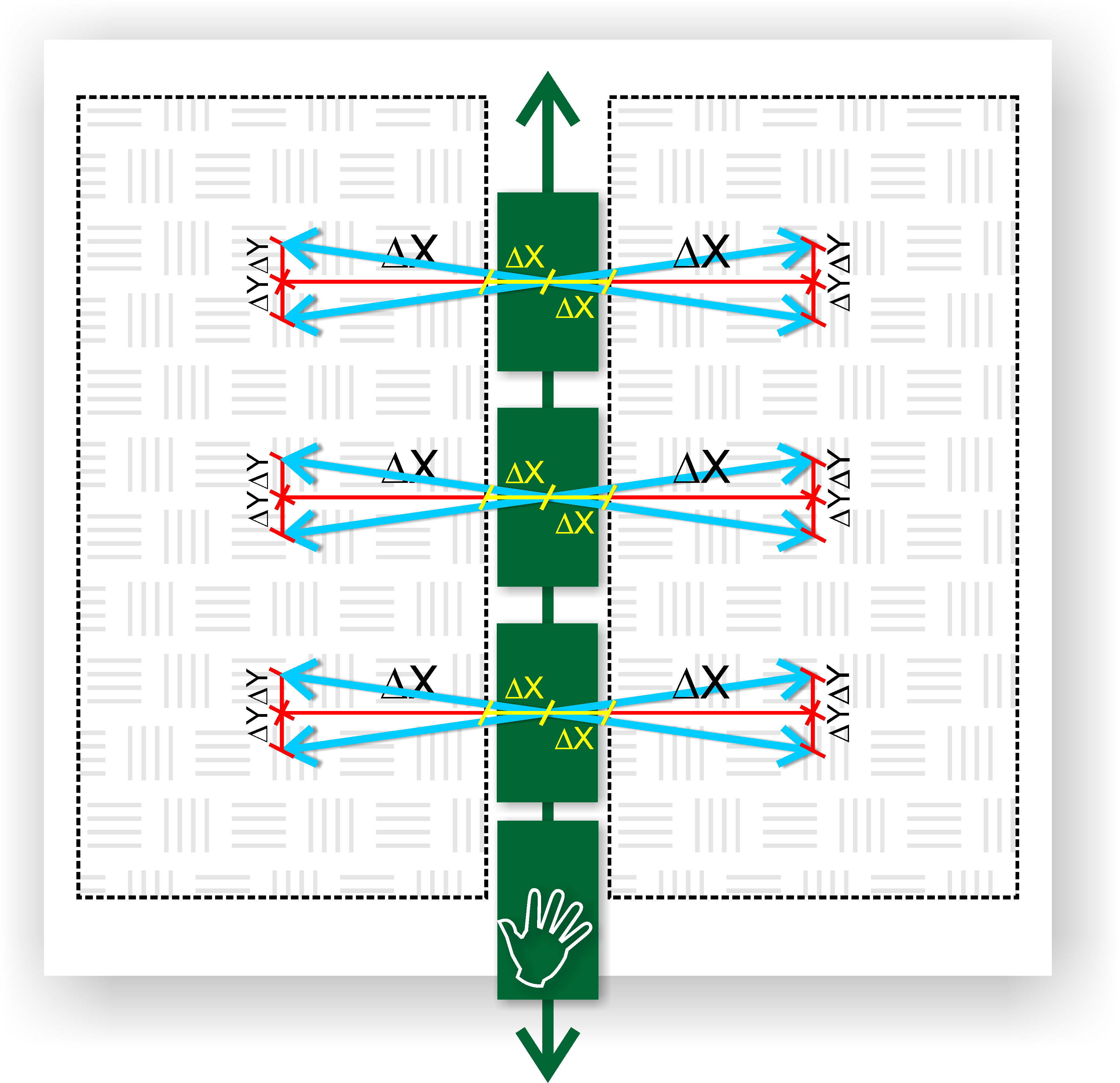
Optimising the PCB Placement
One optimisation is to place the PCB in the middle of the workspace to essentially cut the average move distances in half (except for the PCB half width). We need to look at each quadrant separately, of course:

This will save quite a lot of time, though not the full half, because the acceleration/deceleration phase will now take up a greater fraction of the move (see the previous post)
This arrangement creates another problem: the PCB is now in the middle of the “minefield”. It might be hard to manually interact with it, as the work area is full of part strips with their cover tape removed. Even a small brush with your clothing will create a big mess (I guess that’s also the reason why the Liteplacer article suggests the peripheral placement of the PCB).
Conveyor for the PCB
It wasn’t as straight-forward as depicted here, but eventually I started thinking about a conveyor for the PCB:
This way the PCB can easily be loaded/unloaded. The conveyor would park the PCB safely in the middle of the parts.
As a future option, it would also be possible to move the PCB in Y at certain intervals during the pick&place job, optimising its position for the next bunch of part feeders at similar Y positions. I would have to modify OpenPNP to trigger these conveyor moves and to order the placements in the job for similar feeder Y positions. This seems entirely possible.
Larger Y
To increase the usefulness of this (future) option, I even increased the size of my Y axis from 500mm up to 750mm rails. The former bottleneck was becoming an asset.
The design was taking shape.
Leave a Reply