Grounding the Machine
| Part 10 of the build documentation. You may want to check out the intro first. |
There are three reasons (known to me) why various parts of the machine should be grounded:
Firstly, exposed conductors (i.e. metal parts) of your machine should be grounded for safety reasons in order to trigger the over current or residual current breakers when a fault occurs. Make sure to have seen the post about Electrical Safety including the disclaimer.
Secondly, cable shields, housings etc. should be grounded to form a Faraday cage in order to block electromagnetic fields created by the electronics and motors of the machine to prevent EMI which might distort signals etc.
Thirdly, the surfaces and nozzles of your machine should be grounded to prevent ESD discharges into your sensitive electronic parts.
Problems and solutions (numbers for reference in discussions):
- It is important to realize that the gantries of your linear actuators may not make contact to the rails. In common maker solutions (MakerSlide, V-Slot) the wheels are made of plastic (Delrin) and don’t conduct electricity. Also most extrusions are anodized and surfaces won’t conduct. Whether the more expensive linear rails conduct electricity or not, I don’t know.
- The belt is rubber-like and the friction might actually influence high voltages through Electrostatic Induction creating an ESD hazard.
- ESD grounding often includes a rather high Ohm resistor to ground (1MΩ typical) to allow for slow discharges/low discharge current in order not to damage parts. This contradicts Safety and EMI grounding requirements where low impedance grounding is essential.
- It can be easily seen that if your body’s resistance in the order of 1kΩ forms a circuit the ground, a 1MΩ grounding resistor will not protect you. I opted for safety.
- The USB Port includes a ground connector and shield that is connected to the computer’s ground. As the computer is often connected to mains ground through a different cable/extension/plug this might create a nasty “ground loop” that can damage your computer or controller (speaking from experience).
- Warning: The USB ground problem is not solved in the above illustration. In my machine I use the Azteeg X5 GT Smoothieware controller that has an USB isolator built-in. Using Ethernet instead of USB does provide similar isolation. Otherwise you could use an external USB isolator.
- Large currents create ground offset, as even milliohm resistances in wires and connectors create significant voltage differences (U = I × R). Inductances such as with long wires dramatically amplify the effect for rapidly switching currents, creating “ground bounce“.
- Ground offsets may be handled by laying out your ground wiring in a star topology. But where is the centre of the star?
- You also need to connect mains ground to the “DC minus”, otherwise your power supply DC side is floating!
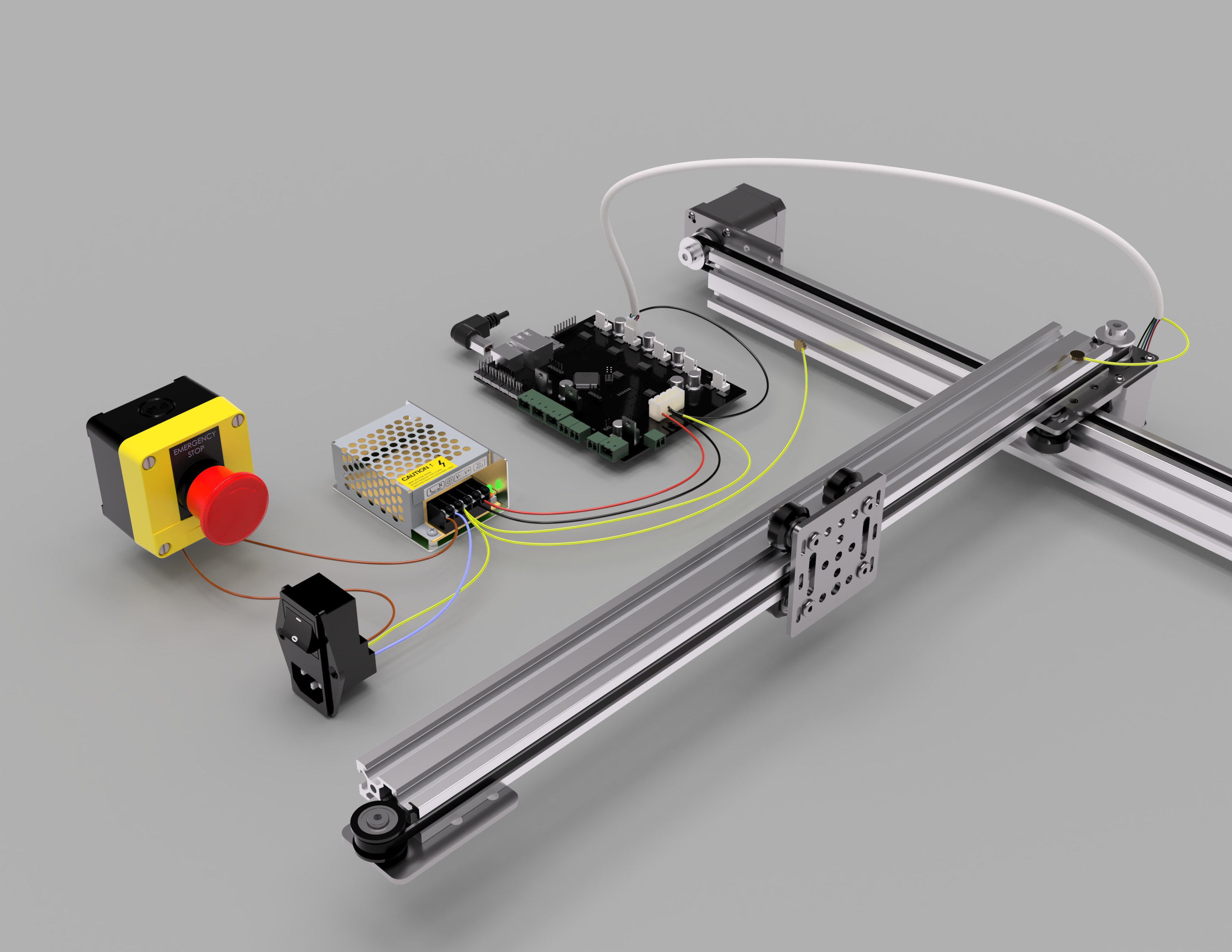
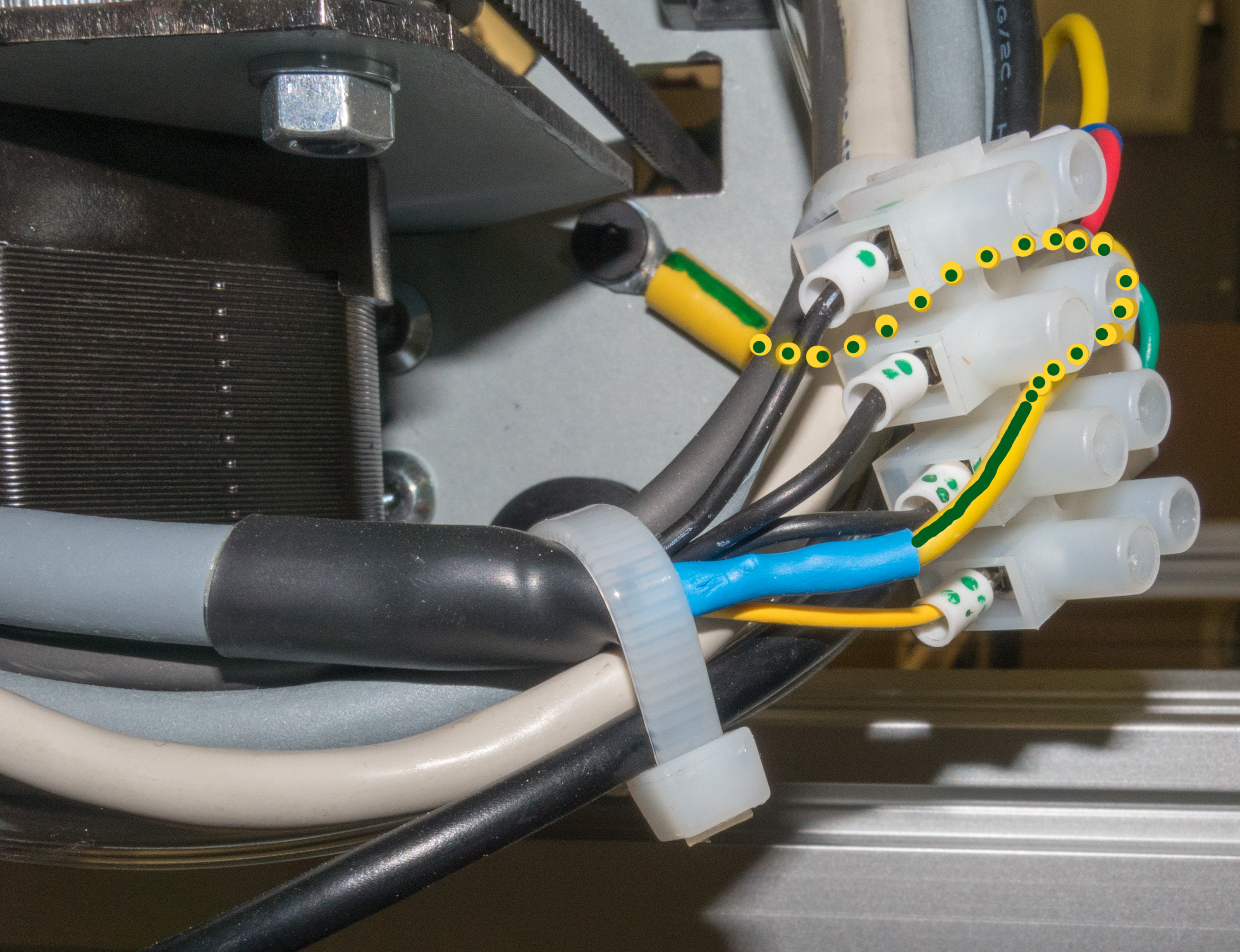
- The question was: do I connect mains ground to DC minus at the power supply or at the controller side? The DC minus wire (thick black wire in photos and illustration) will carry the sum of all currents. It is most likely to exhibit a ground offset (or even a ground bounce if rapidly changing). Therefore to eliminate this ground offset, I chose to connect mains ground to DC minus at the controller side (actually I came to this conclusion only later). This way the supply DC minus may shift or bounce into the minus but no other circuit, signal or shield is affected.
- All subsequent grounding connections ray out from the controller, creating a “star-of-stars” ground configuration, strictly speaking, as the “super-star” is at the power unit and a “sub-star” is created for Analogue Ground AGND signals. This also includes all cable shields.
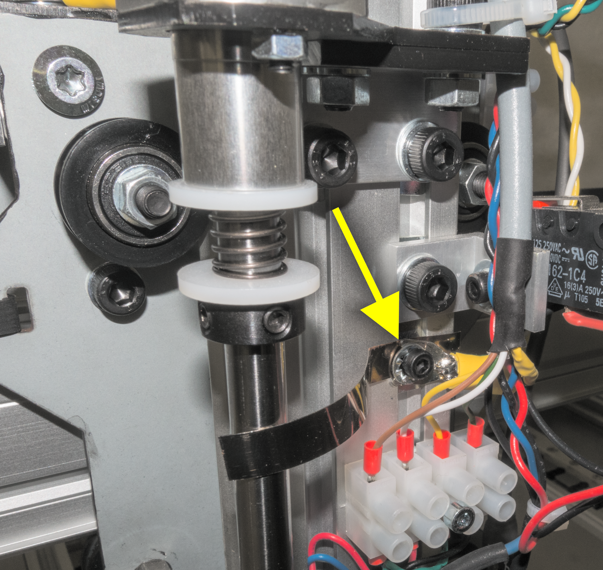
- From the (motor) cable shield (at the other end of the cable) each axis extrusion and/or plate is grounded. I used special drag chain cables with sturdy braided shielding that can be “unbraided” at the end and twisted into a strong wire and sheathed in a heat shrink tube.
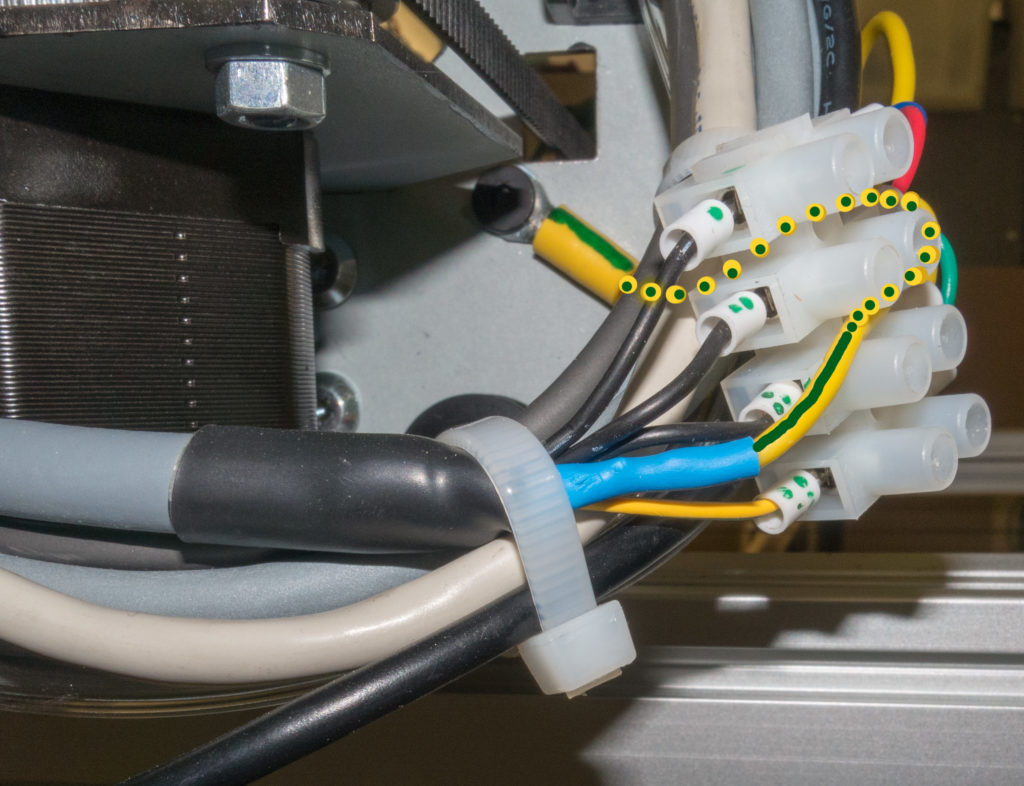
- Screws seem to reliably break up the anodizing and will make contact with the metal. I added serrated lock washers to make sure.
- This pattern “stars out” to each axis. The “C” axis motor cable shield grounds the rotating nozzle shaft where the nozzle tip holder is screwed in and consequently makes contact with the nozzle tip. Conveniently the Liteplacer already has a spring to the rotating rod taking out any slack but also making good contact.

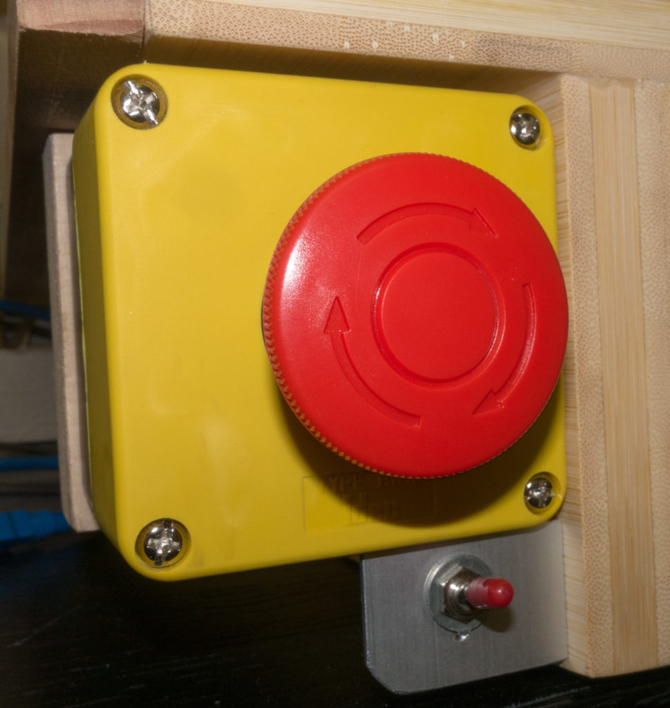
- The Emergency Stop switches off the mains power.
- Pros: the mains current is small and the usual Emergency stop buttons are rated for both voltage and current (contrarily my power supply is rated at 15A so a secondary side switch would have to be enormous). With the Emergency Stop on the primary side, electrical emergencies are also covered.
- Cons: The machine will continue to work for a moment before the capacitors of the power supply are drained. However, this is only the case when the motors are off and only small currents flow. With moving motors/large currents the stop is quite immediate.
- I added a switch to the reset line of the controller (in a separate shielded cable!) so I can quickly reset the board after a config.txt change. Keeping the board in reset for a longer time is useful when you have to sort out Windows sitting on a dead USB connection. I always have to quit and restart OpenPNP when I reset the board.
- The symbolic illustration (image at the top↑) shows the wiring with one axis as an example. Be sure to mind the USB ground issue (not really shown there). The image can be clicked to enlarge.

I don’t know whether all this is correct let alone [safety] standards conformant. It just seems logical.
All inputs welcome!
Special Credits:
- apertus Liteplacer PnP Notes
- Power Supply by Serj Minin on GrabCAD
- Smoothieboard 5Xc V1.0b by Chris on GrabCAD
- USB Type-B – Male – 90° by Mehmet Emre FIRAT on GrabCAD
- IEC connector with switch combo by Robert Stein on GrabCAD
- EMERGENCY STOP by John on GrabCAD
- OpenBuilds Parts Library
Leave a Reply